Raspberry Pi LED Badge Weather Warning Application
A couple of years ago at the Dayton Hamvention, I purchased a number of LED Badges with the intention to hack them for usage with Raspberry Pi's. One of the use cases was to use the RPi to drive the LED Badge to display weather alerts and warnings. You probably noticed at the top of my website that I display weather advisories, watches, and warning as a marquee. But what if I am not looking at my website? How would I know whether there were alerts for where I live. Thus the idea to use the RPI and the LED Badge to to create a weather alert scrolling message board and place the system in my sunroom where it would update 24/7.
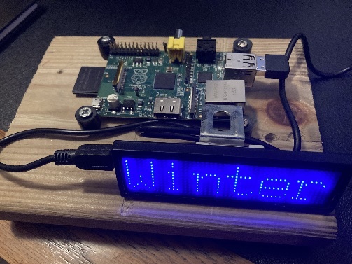
The pieces of the project were simple. A Raspberry Pi, and it can be an original Pi like I used, and an LED Badge like the one I show below;
These LED badge displays typically have a USB socket for charging and programming, and appear to a PC or Pi as a virtual serial port.
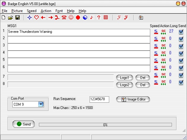
The badges come with Windows drivers and software to download messages to the device. The intention with the software is that you type in your message, download the message to the badge, then unplug and run the display from its internal battery. Messages are stored internally in flash memory so the device can be powered off and it will retain the message.
For my purposes, I need the Raspberry Pi to monitor weather alerts from the local National Weather Service and search for my county in lists of possible weather alerts. Once my county has been identified, the Pi will upload the message to the display and scroll the alert until a new alert message is identified.
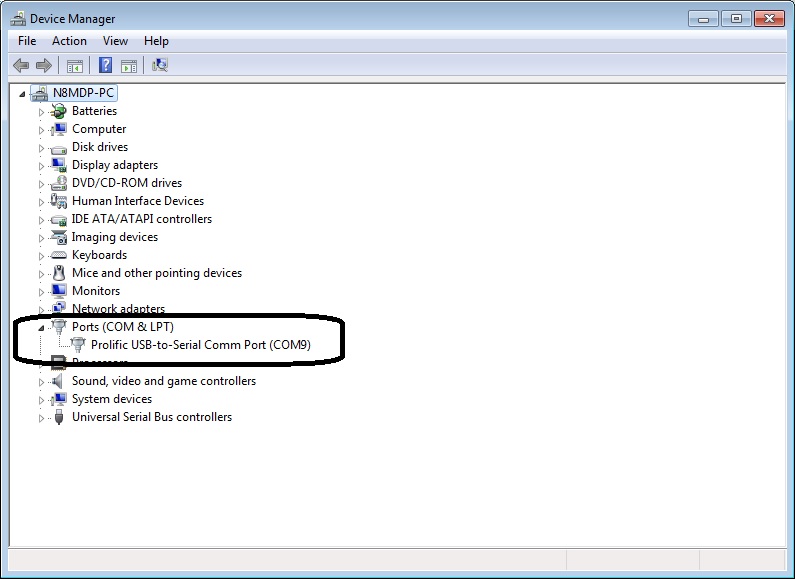
So the first job was to get the device running on my Windows PC. The device installed as a serial device (the common Prolific PL2303 driver) and the supplied software successfully sent messages to it:
One of the problems with these LED Badges is that you don't know how the data is encoded when you send a message from the software to thge badge over USB.
So with the software working, we need to take a look at what it was sending to the device. To do this, I needed to obtain a serial monitor program. Based on other references online, I downloaded HHD Software Device Monitoriing Studio. This is a great tool for snooping on devices that use serial control such as USB devices.
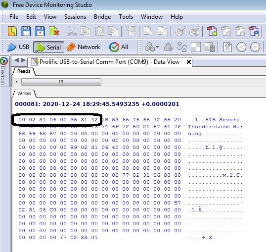
I'm not going to go through the details of how to run the monitoring software but the important result is that you get a data view of the data transfered. To get the first results, I used the LED Badge software to send the message: Severe Thunderstorm Warning. The monitoring software captured the following:
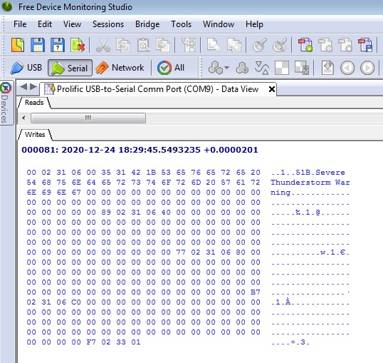
It's very clear where the message is in the packet transfer. But there are other pieces of data, at least for my badge to be aware of. My badge allows multiple messages to be uploaded at one time. If you look carefully, there are blank areas where no characters were sent yet a block of '00' hex values are sent. This is important when writing the Python script that I developed for this application.
I should mention that a LED badge you have may not behave and transfer packets of data the same as mine. At least my analysis may help you to get yours working as well. Let's breakdown the data packet to explain what was sent.
The first set of 8 bytes (00 02 31 06 00 35 31 42 in Hex) appears to be an 8-byte header that is sent everytime a single message is sent. I duplicated this with other message tests. So every packet that is sent by the Pi must start with these first 8 bytes.
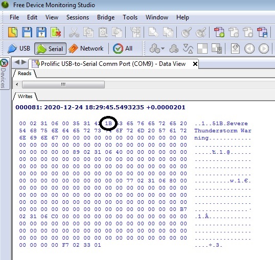
The next byte of interest is 1B Hex. Based on other message tests, this is a character count for the first message sent. Knowing this, we will be able to write a formula in Python to calculate the message length and include it in the data packet. For my message test: Severe Thunderstorm Warning, this is a 27 character message. 1B hex is 27 integer.
The next 27 bytyes sent is the message, from hex 53 to hex 68.
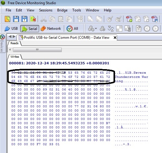
The first message block is a total of 60 bytes. Given that my test message was 27 characters, the remaining characters must be 00 hex and it is 60 - 27 = 33 characters to transmit.
The next byte to be concerned with appears to be a checksum byte. In the case for the Severe Thunderstorm Warning message, 89 Hex.
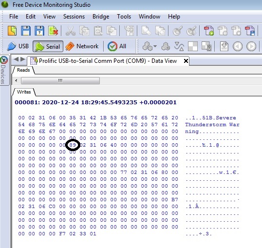
Testing different messages resulted in very different byte values that were sent. I tried for days to recreate how this byte was calculated, but was not successful. In order to send the correct checksum value, I had to confirm the value of all the alert messages I wanted the Python program to display. In my program, this was a total of 39 alert messages. I'll talk more about the alert messages and where they will be coming from later.
You will see in the Python program the different checksum values.
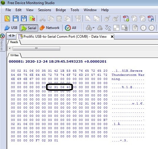
The next 4 bytes is another header, 02 31 06 40. This is a header for the second message that 'could' be uploaded into the badge memory. Whether you send a second message or not, the header must still be sent.
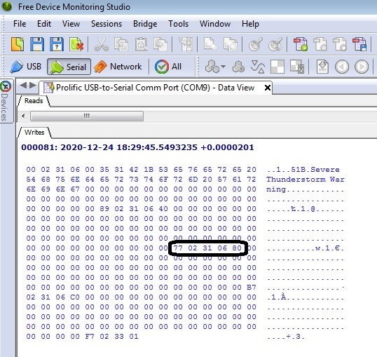
The next group of 64 bytes must be 00 hex since no message characters are sent. After the 64 bytes are sent, another checksum and 4 byte header is sent (77 02 31 06 80). Since I am not sending another message, I can always send the byte 77 as the checksum. I verified this in other test runs.
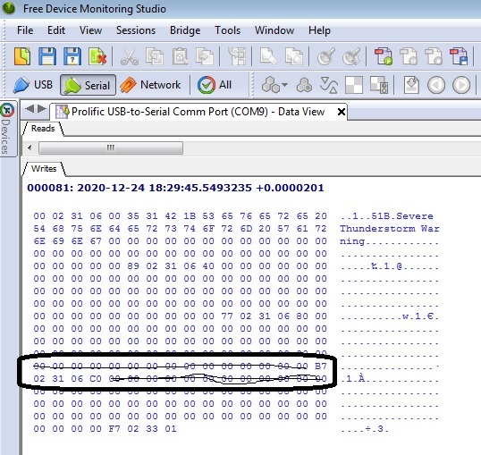
The next group of 64 bytes must be 00 hex since no message characters are sent. After the 64 bytes are sent, another checksum and 4 byte header is sent (B7 02 31 06 C0). Since I am not sending another message, I can always send the byte B7 as the checksum. I verified this in other test runs.
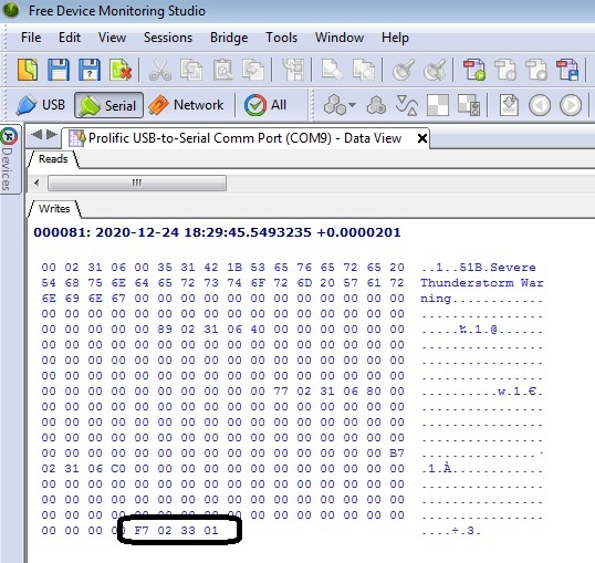
FInally, another group of 64 bytes must be 00 hex since no message characters are sent. After the 64 bytes are sent, another checksum and 3 byte header is sent (F7 02 33 01). Since I am not sending another message, I can always send the byte F7 as the checksum. I verified this in other test runs.
Understanding the packet structure, I needed to determine the messages I would send. The National Weather Service has a listing of standardized watches, warnings, advisories, and statement that they issue thorugh their RSS service. You can find this listing at https://www.weather.gov/help-map. The listing also provides priority levels that was helpful in my Python code should I recieved multiple warnings and watches for my county. This way, I display the highest prioirity message.
Here examples of messages and their priority level:
'Tornado Warning, 2
'Severe Thunderstorm Warning,4
'Flash Flood Warning, 5
'Blizzard Warning, 23
'Snow Squall Warning, 24
'Ice Storm Warning, 25
'Winter Storm Warning, 26
Tornado Watch, 44
As a I said previously, for the 39 messages I planned to use, I had to test each and every one of them to get the checksum value to send when that message needs to be displayed. This is where the serial monitoring sofware came in real handy. Here are some examples from my Python program:
# Checksum based on NWS listing. This section assigns the Checksum value
'Tornado Warning': '\xBB',
'Severe Thunderstorm Warning': '\x89',
'Flash Flood Warning': '\xEA',
'Blizzard Warning': '\x27',
'Snow Squall Warning': '\x21',
'Ice Storm Warning': '\x2C',
'Winter Storm Warning': '\x97'
Now the fun begins. The Python Code. I will break down the code so you can understand each section and what I did.
***** Python Code for running the Weather Alert badge on the RPi.
The first section is to import that necessary libraries. One of the most important libraries is the 'feedparser'. This is needed to parse the RSS feed from the NWS.
import serial
from time import sleep
import feedparser
import time
import datetime
The next section of code defines and assigns the priority level of the messages based on the NWS listing.
def alertType_to_priorityNum(alertmessage):
switcher = {
# Priority level based on NWS listing. This section assigns the priority level.
'Tornado Warning': 2,
'Severe Thunderstorm Warning': 4,
'Flash Flood Warning': 5,
'Blizzard Warning': 23,
'Snow Squall Warning': 24,
'Ice Storm Warning': 25,
'Winter Storm Warning': 26,
'High Wind Warning': 27,
'Flood Warning': 38,
'Lake Effect Snow Warning': 42,
'Excessive Heat Warning': 43,
'Tornado Watch': 44,
'Severe Thunderstorm Watch': 45,
'Flash Flood Watch': 46,
'Wind Chill Warning': 49,
'Extreme Cold Warning': 50,
'Hard Freeze Warning': 51,
'Freeze Warning': 52,
'Red Flag Warning': 53,
'Freezing Rain Advisory': 65,
'Winter Weather Advisory': 66,
'Lake Effect Snow Advisory': 67,
'Wind Chill Advisory': 68,
'Heat Advisory': 69,
'Flood Advisory': 73,
'Dense Fog Advisory': 79,
'Frost Advisory': 91,
'Blizzard Watch': 99,
'Winter Storm Watch': 103,
'Flood Watch': 108,
'High Wind Watch': 109,
'Wind Chill Watch': 112,
'Lake Effect Snow Watch': 113,
'Hard Freeze Watch': 114,
'Freeze Watch': 115,
'Air Quality Alert': 123,
'Air Stagnation Advisory': 124,
'None': 200,
'No Watches, Warnings or Advisories': 900
}
return switcher.get(alertmessage)
The next section of code assigns the checksum values to each of the individual messages.
def alertType_to_checkSum(alertchecksum):
switcher = {
# Checksum based on NWS listing. This section assigns the Checksum value
'Tornado Warning': '\xBB',
'Severe Thunderstorm Warning': '\x89',
'Flash Flood Warning': '\xEA',
'Blizzard Warning': '\x27',
'Snow Squall Warning': '\x21',
'Ice Storm Warning': '\x2C',
'Winter Storm Warning': '\x97',
'High Wind Warning': '\x18',
'Flood Warning': '\xD6',
'Lake Effect Snow Warning': '\x9E',
'Excessive Heat Warning': '\x3C',
'Tornado Watch': '\xDA',
'Severe Thunderstorm Watch': '\xA8',
'Flash Flood Watch': '\x09',
'Wind Chill Warning': '\x85',
'Extreme Cold Warning': '\x65',
'Hard Freeze Warning': '\xE8',
'Freeze Warning': '\x44',
'Red Flag Warning': '\x9A',
'Freezing Rain Advisory': '\x4A',
'Winter Weather Advisory': '\xD0',
'Lake Effect Snow Advisory': '\x1A',
'Wind Chill Advisory': '\x01',
'Heat Advisory': '\xDF',
'Flood Advisory': '\x52',
'Dense Fog Advisory': '\x8D',
'Frost Advisory': '\x6C',
'Blizzard Watch': '\x46',
'Winter Storm Watch': '\xB6',
'Flood Watch': '\xF5',
'High Wind Watch': '\x37',
'Wind Chill Watch': '\xA4',
'Lake Effect Snow Watch': '\xBD',
'Hard Freeze Watch': '\x07',
'Freeze Watch': '\x63',
'Air Quality Alert': '\x2D',
'Air Stagnation Advisory': '\xBB',
'None': '\x73',
'No Watches, Warnings or Advisories': '\x7C'
}
return switcher.get(alertchecksum)
The next definition is the primary section that writes the packets of data to the LED badge through the USB port. You should recognize many of the bytes we obtained in the analysis from the serial monitor data dump.
def write_string_to_LEDbadge(alertMessage):
#Open the USB serial port
ser=serial.Serial('/dev/ttyUSB1', 38400)
print ('Alert Message :', alertMessage)
# Block Group 1: Send the first 8 bytes
ser.write(b'\x00')
ser.write(b'\x02')
ser.write(b'\x31')
ser.write(b'\x06')
ser.write(b'\x00')
ser.write(b'\x35')
ser.write(b'\x31')
ser.write(b'\x42')
# Determine the length of the alert message string. Convert to hexadecimal
wxStringLength = len(alertMessage)
print('String Length = ',wxStringLength)
# Block 2 is the hex equivalent of number of characters to send. Write the 1 byte.
byteBlock2 = chr(wxStringLength)
arr2 = bytearray(byteBlock2, 'utf-8')
ser.write(arr2)
# Block 3: Need to loop through the number of characters in the string. Write them.
for x in range(len(alertMessage)):
byteBlock3 = alertMessage[x:x+1]
ser.write(bytearray(byteBlock3,'utf-8'))
#Block 4: Send empty characters. Depends on the length of the wx_string.
# Take 60 characters less the wx_string to know how many blank characters are sent
blankChars = 60 - len(alertMessage)
print(blankChars)
for x in range(blankChars):
ser.write(bytearray('\x00','utf-8'))
#Block 5: Send the message checksum.
alertChecksum = alertType_to_checkSum(alertMessage)
print('AlertChecksum = ', alertChecksum)
# For some reason, I had to use the "latin_1" encoding for hte byte to send correctly.
ser.write(bytes(alertChecksum, 'latin_1'))
#Block 6: Send the next 4 header bytes
ser.write(b'\x02')
ser.write(b'\x31')
ser.write(b'\x06')
ser.write(b'\x40')
#Block 7: Send empty characters
for x in range(64):
ser.write(bytearray('\x00','utf-8'))
#Block 8: Send the next checksum and 4 header bytes
ser.write(b'\x77')
ser.write(b'\x02')
ser.write(b'\x31')
ser.write(b'\x06')
ser.write(b'\x80')
#Block 9: Send empty characters
for x in range(64):
ser.write(bytearray('\x00','utf-8'))
#Block 10: Send the next checksum and 4 header bytes
ser.write(b'\xB7')
ser.write(b'\x02')
ser.write(b'\x31')
ser.write(b'\x06')
ser.write(b'\xC0')
#Block 11: Send the next block of 64 empty characters
for x in range(64):
ser.write(bytearray('\x00','utf-8'))
#Block 12: Send the final 4 bytes
ser.write(b'\xF7')
ser.write(b'\x02')
ser.write(b'\x33')
ser.write(b'\x01')
#Close the serial port
ser.close()
The next section is a display timer. Every 2 minutes, the display will update should a new prioirty message be recieved.
def loop_display():
now=time.time()
timer = 0
while timer < 120:
end = time.time()
timer = round (end-now)
Now comes the main loop. This loop goes out and gets the latest NWS RSS feed for Ohio, parses the feed looking for the county I am in, adjusting the priority level if higher priority messages come in, and then send the message to the definition which writes the message to the USB port. I tried to comment the code as much as possible.
print ('Starting loop')
loopcntr = 0
#Main Code Here
while True:
print('Next loop')
loopcntr +=1
print(loopcntr)
# Reset Geauga Found flag. This flag tracks if there are alerts or not for my county.
geauga_found_flag = 0
# Get the RSS feed from NWS for Ohio
alertFeed = feedparser.parse("http://alerts.weather.gov/cap/oh.php?x=0")
# Obtain number of entries in the feed. This is a normal RSS action
num_entries = len(alertFeed['entries'])
# Reset the Priority Number variable to 900. This number will reflect No Watches/Warnings
priorityNum = 900
priorityChecksum = '\x00'
# Loop to find all occurences of Geauga County in the feed, if any, even if there are watches and warnings in the same feed. This is how we will set the priority levels.
for nws_entry_ID in range(num_entries):
if alertFeed['entries'][nws_entry_ID]['title'] == 'There are no active watches, warnings or advisories':
break
areaDescription = alertFeed['entries'][nws_entry_ID]['cap_areadesc']
print (areaDescription)
geauga_found = alertFeed['entries'][nws_entry_ID]['cap_areadesc'].find('Geauga')
print(geauga_found)
if geauga_found != -1:
geauga_found_flag = 1
alertevent = alertFeed['entries'][nws_entry_ID]['cap_event']
priorityNumNew = alertType_to_priorityNum(alertevent)
if priorityNumNew < priorityNum:
priorityNum = priorityNumNew
alerts = alertevent
# If the Geauga Found flag is never set to 1, then there are no Warnings or Watches. Check it here. Must come after all entries have been scanned.
if geauga_found_flag == 0:
alerts = 'No Watches, Warnings or Advisories'
alertChecksum = '\x7C'
write_string_to_LEDbadge(alerts)
print ('Geauga County : ' + alerts)
#Run the loop timer for two minutes before next update.
loop_display()
That's it! I've been running this code successfully for many months. I set the Raspberry Pi to start the code automatically. So if we lose power or I shut down the Pi, all that needs to be done is to restore power and the Python script starts right up.
You can download the full Python script HERE.
I plan to expand the application by adding bright green, yellow, and red LEDs to indicate no warnings, watches, or warnings.
I hope you found this project interesting. Again, I must reiterate that not every LED badge or message board works the same. Many of the LED boards use the Prolific PL2303 driver, which is very common. Most of these boards are made in China and may use some kind proprietary coding for sending messages to the board. I have a larger LED board that programs completely different than the mini LED Badge I used here. So like me, you may have to do a little bit of hacking and reverse engineering to get your LED board to work.
I hope you enjoyed reading this project.