
Raspberry Pi Lightning Detector
Why build a weather station when you can easily buy one
Ever since I was a kid, I have always been fascinated by storms and especially lightning. Today, with all of my Ham Radio antennas and radios, protecting them from lighting is very important to me. Being able to detect lightning before the storms gets close to my home gives me the opportunity to switch off the antennas in time. I've already had to have my Icom PCR-1000 fixed twice due to lighting crashed and enough static to damage the front end diodes.
Today I rely on severe weather alerts to warn me of pending storms so that I can switch off the antennas. But what if I'm not home? That's why I am building the following lightning detection system so that it will automatically turn off the antennas when lightning is close to my house. If we happenv to lose power at the house, at least the relays on the antenna switch off disconnecting the antennas.
So the following page is dedicated to my building the SwitchDoc Labs lighting detector using the Raspberry Pi.
The SwitchDoc Labs Lightning Detector
What I'm about to build is the Lighting Detector from SwitchDoc Labs using their new Thunderboard. I was impressed with this product as advertised online, so I bought one. The end product will look like this:
This is the Thunderboard which will go inside the housing at the top.
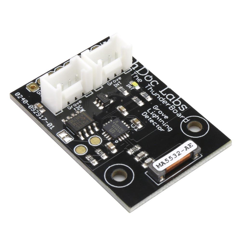
Excerpts from the SwitchDoc Labs describe the Thunderboard as follows:
The Thunder Board Grove I2C Lightning Detector for the Raspberry Pi and Arduino - is a programmable Lightning Sensor board that detects the presence and approach of potentially hazardous lightning activity in the vicinity and provides an estimation on the distance to the head of the storm. The embedded lightning algorithm checks the incoming signal pattern to reject the potential man-made disturbers and various noise sources.
How the heck do we detect lightning? You would think it would be pretty easy, but it turns out it is not. It's not just like a giant spark. Well, it is a giant spark, but there are lots of other things that make electrical noise that can be confused for lightning. Your computer (even your Raspberry PI and Arduino!), your car, the motor in your refrigerator, your cell phone, your computer monitor, your AM/FM radio and even your TV. They all make electrical noise that can be confused with Lightning.
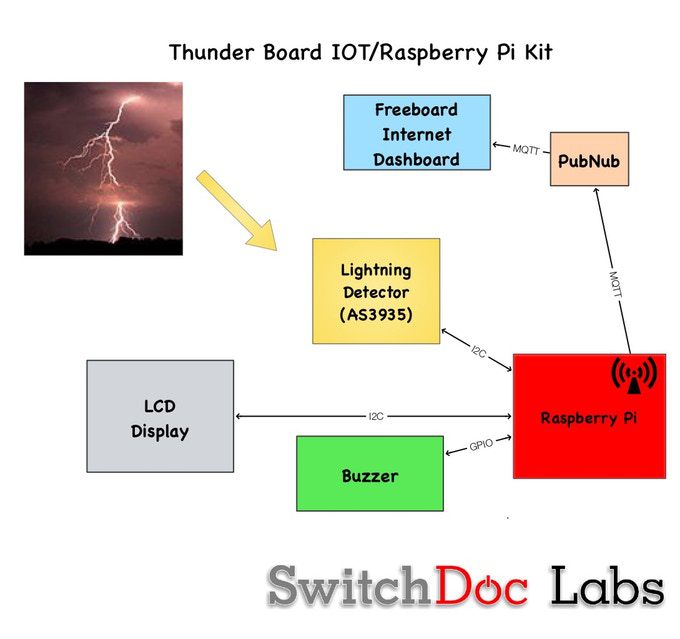
The Thunder Board is an I2C device and detects Lightning and provides a distance estimate to the 'leading edge' of an incoming storm.
The block diagram of the Lightning Detector is as follows. Click on image to enlarge.
According to SwitchDoc Labs, the entire hardware kit is as follows:
| Item # | Item | Image |
|---|---|---|
| 1 | Thunder Board Lighting Detector | |
| 2 | Pi2Grover Board | 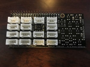 |
| 3 | Grove LCD Display with Backlight | 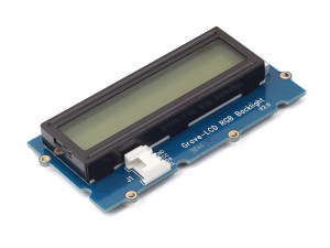 |
| 4 | Grove Buzzer | 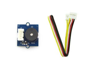 |
| 5 | Additional Grove Cables (2) 30cm Cables | 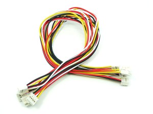 |
| 6 | Raspberry Pi 3 or better! | 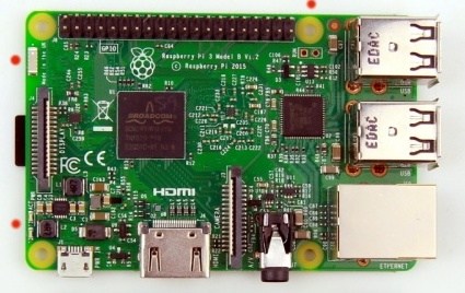 |
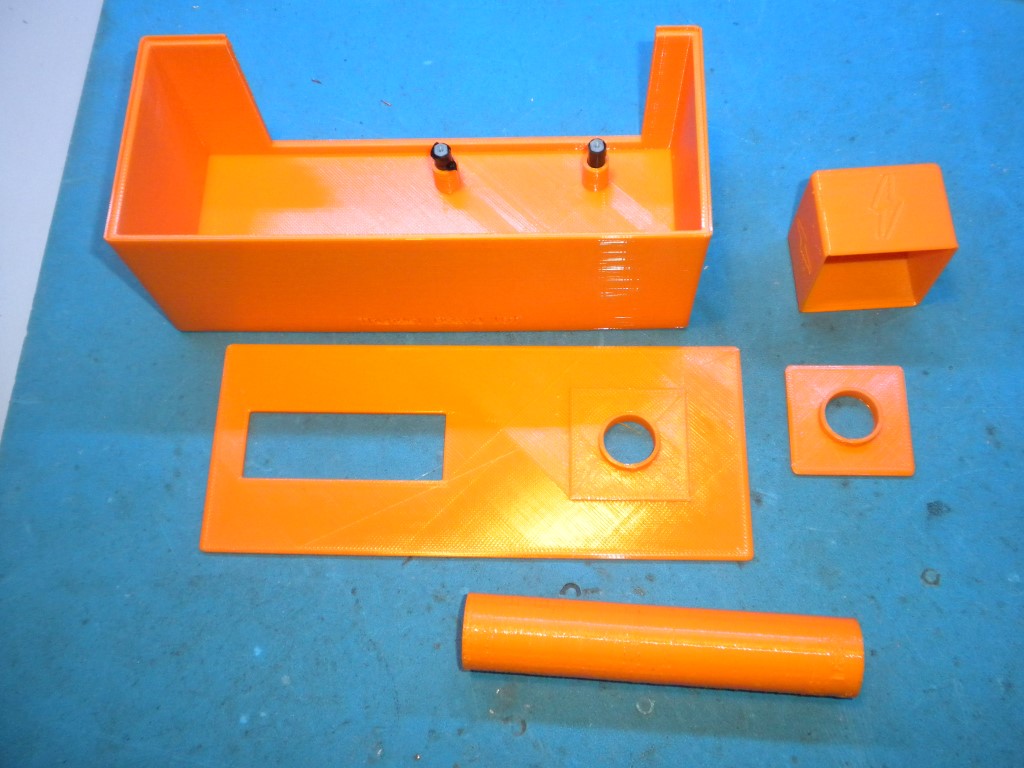
| 7 | 3D-Print Files available at GitHub |  |
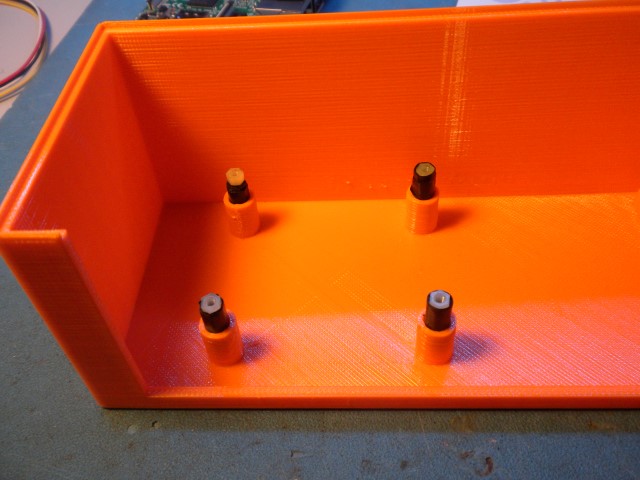
I contracted to my daughter to make the 3D printed parts which are shown here:
Now that I have all of the pieces / parts needed to start the project, the next phase is to initialize the Raspberry Pi 3 and install the software so I can do initial testing.
Installing the software on the Raspberry Pi 3
While SwitchDoc Labs in their second tutorial on this project puts all of the hardware together, I decided to install the software on the Raspberry Pi 3 first. I followed the instructions located in the Switcdoc Tutorial 2 for installing the software. I'm not going to repeat the instructions here. Follow the appropriate instructions for installing an operating system on the RPi. A decent set of instructions can be found here.
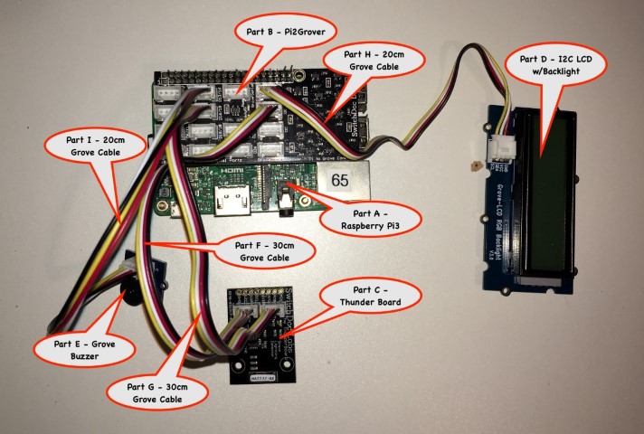
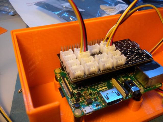
Once I had the software installed, it's important to start checking if all of the parts are recognized by the Raspberry Pi. So I pre-wired all of the boards before installing into the 3D printed box. The wiring diagram is shown below. Click on image to enlarge.
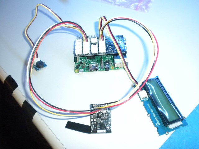
The wired up system looks as follows. Click on image to enlarge.
With everything wired up, I powered up the Raspberry Pi to start my testing. to start the testing, you need to open a terminal window. Or in my case, I am using SSH for which I use the program 'PUTTY' and connect via an IP address. In either PUTTY or a terminal window on the PI, you type:
sudo i2cdetect -y 1
The results should look like the following:
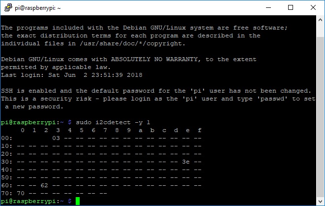
Depending on your Raspberry Pi, you may not see 0x03 or 0x70. If you don't see 0x3e and 0x62, then your LCD is not connected correctly. Note, you will not see the ThunderBoard in this test. By the way, I had to disconnect the buzzer as it was quite annoying since it was constantly buzzing.
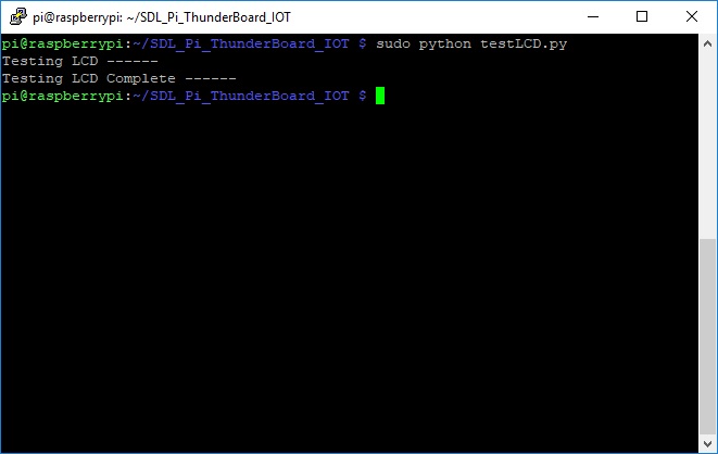
To test the LCD display, in either PUTTY or a terminal window, you type:
sudo python testLCD.py
You should see the display changing colors and printing text on the display: "Going to sleep in xx..." where the xx is a countdown of numbers.
Once the test is over, you will see in PUTTY or the terminal window:
To test the ThunderBoard, you type in PUTTY or a terminal window:
sudo python testThunderBoard.py
You should definitely see the first line. It should say 0x02 or 0x03 depending on the version of the Thunder Board that you have.
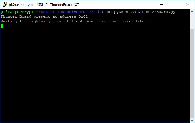
You may see more lines if your environment is especially electrically noisy. Hold it up against a monitor may trigger the noise system. So far, so good!
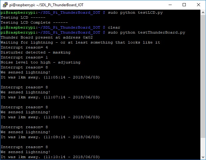
You should be able to get a noise trigger by holding it close to your phone or computer monitor, but not guarantees unfortunately. Depends on too many factors. The only way to fully test the devices is to wait for a thunderstorm or use the Thunder Board Lightning Simulator.
Interesting that after a few minutes, the software test did start to report something. My guess is that my ThunderBoard was in close contact with some noise generators around my workbench.
Looking good. At this point, I'm satisfied that things are beginning to work. Now to install the hardware into the 3D printed case.
Installing the hardware into the 3D printed case
Using the instructions from Tutorial 2 on the SwitchDoc Labs website, here is what I had to do.
| Step # | Instruction | Image |
|---|---|---|
| 1 | Removed power from the Raspberry Pi from my prior testing. Be sure to shut it down before you remove power! | |
| 2 | If any of your 3D parts are too tight, you can use a fingernail file to slightly mold them. Or as I did, my standoffs were too small. So I wrapped them with electrical tape so they would fit snug into the mounting holes. Install the Raspberry Pi into the 3D printed case. |
 |
| 3 | Install the Raspberry Pi into the 3D printed case. I used nylon standoffs and screws. | 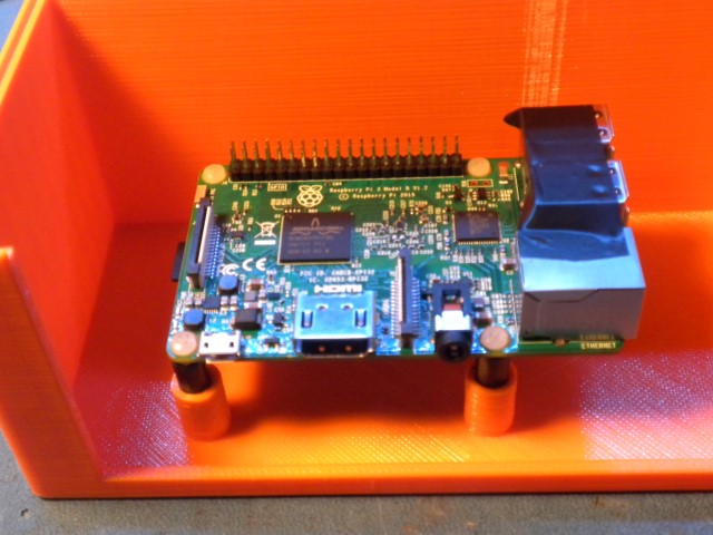 |
| 4 | Take the Pi2Grover board and align the pins on the Raspberry Pi 3 GPIO header accurately and the carefully push down the Pi2Grover board on to the Raspberry Pi 3 board. I actually did this above when I tested the boards. Note that the end of the Pi2Grover board that hangs over the USB and Network plugs on the Raspberry Pi 3 has no pins on the bottom of the Pi2Grover board so it can't short out. But I put electrical tape on the USB connectors just in case! | 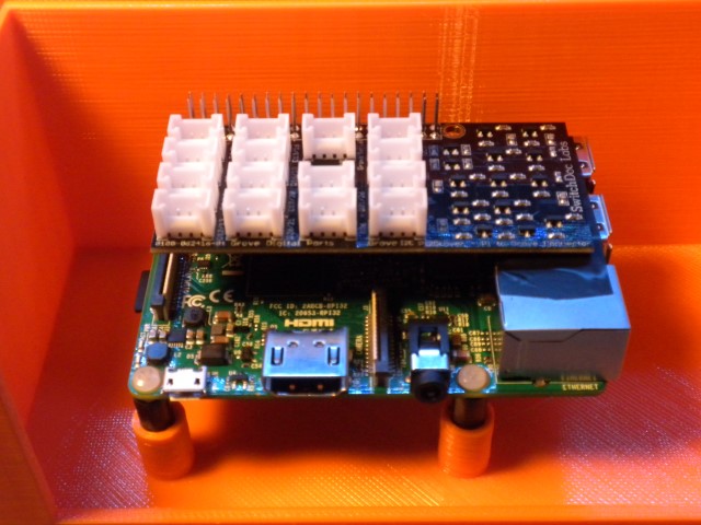 |
| 5 | Take a 20cm Grove Cable plug it in the upper right Grove connector on Pi2Grover labeled I2C and connect the other end to the I2C LCD 2/Backlight. | 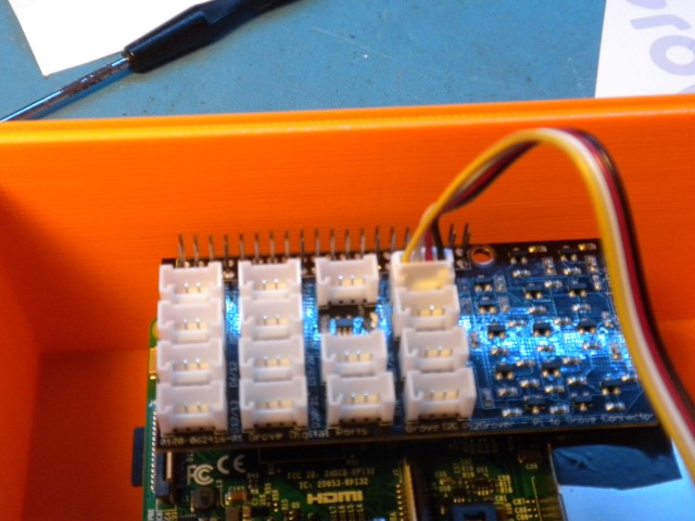 |
| 6 | Take a 30cm Grove Cable and plug it into Pi2Grover label I2C under the Cable in Step 3 above. Take a 30cm Grove Cable and plug it into Pi2Grover in the plug labels D16/19. Make sure you know which cable is which because you will need to feed it though the top case cover. |
 |
| 7 | Put Non-Conductive tape (Like electricians tap, painters blue tape or scotch tape) over the conductors on the LCD Board and over the exposed contacts and metal on the Raspberry Pi as shown. This is in case the LCD is pushed back into the box by mistake when the Kit is powered up. Just a caution! | 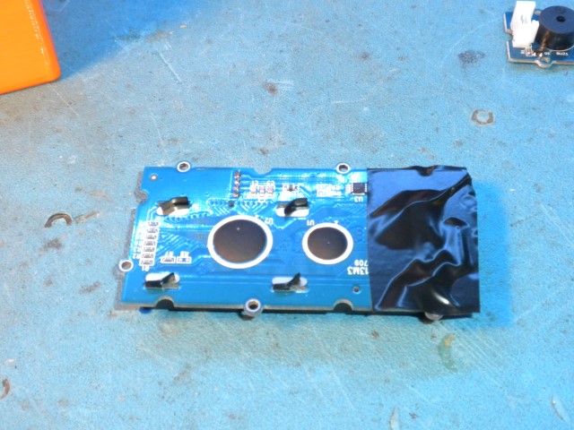 |
| 8 | Please the Grove Buzzer in the slot as shown. Don't plug it in yet! Wait until you have installed the software, otherwise, it will buzz all the time. | 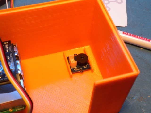 |
| 9 | Push the I2C LCD w/Backlight into the top of the Box as shown. Watch the Orientation. If it is too tight, use a nail file to shave a bit off. Too loose? Tape it in. By the way, I disconnected the Grove cable from the Pi2 Grover board to make it easy to tape the display to the cover panel. Once I was done, I plugged it back into the Pi2Grover board. | 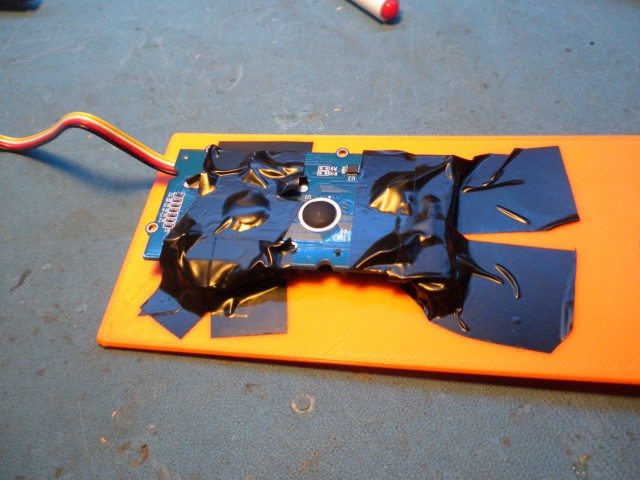 |
| 10 | Now route the cables intended for the ThunderBoard through the hole in the top and then up the 3D tube (placing the tube on the stand on the top of the box), then through the pylon stand (putting the pylon stand into the tube) and then replugging the cables into the Thunder Board. MAKE SURE YOU PLUG THE CABLES INTO THE RIGHT GROVE CONNECTORS. I used a little sticky tab to identify one of the cables. | 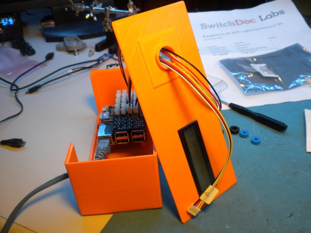 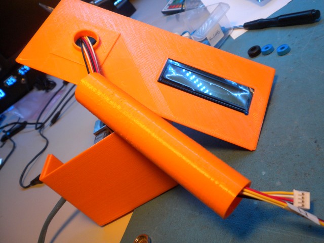 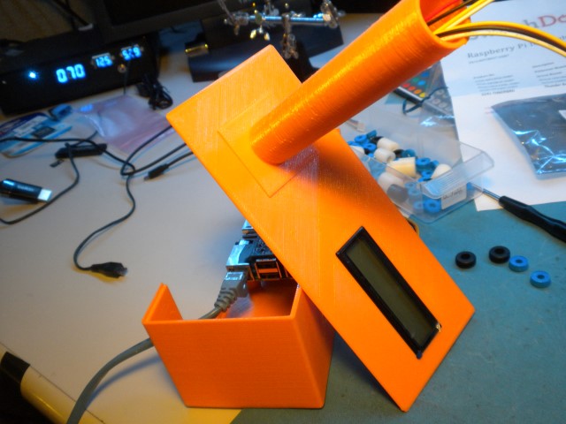 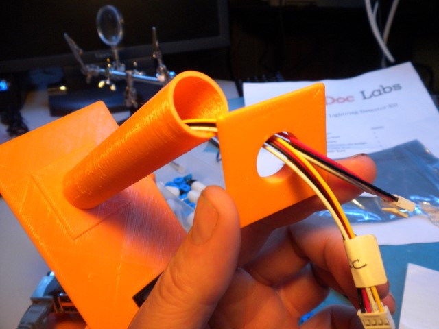 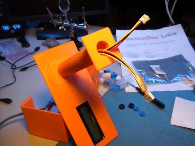 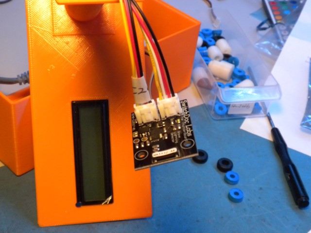 |
| 10 | Insert the ThunderBoard into the top box part as shown. | 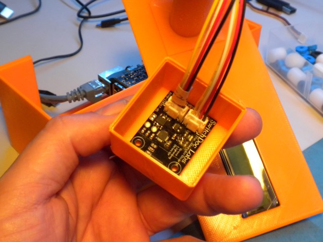 |
| 10 | Snap the top of the box on to the box bottom and then snap the lightning board box on the top of the lightning pylon. You may have to apply some tape to the box top cover as I did in order to keep the top cover on. Not a big deal. At some point, will have to connect the buzzer and will have to lift off the top cover. You are now done. | 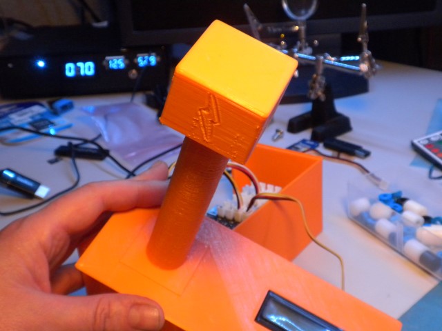 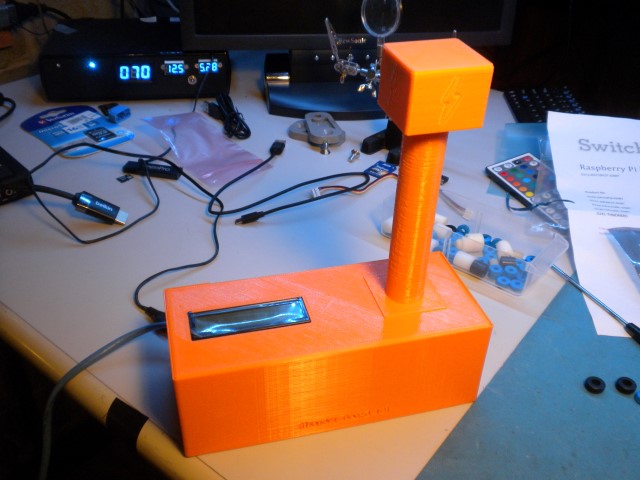 |
That's all for the initial assembly. Again, I will install the Grove Buzzer later and the remaining 20cm Grove Cable. At this point, I don't want the buzzer to buzz incessantly while I complete the software install. Believe me, it's irritating as I found out when I was testing the system!
Auto starting the Lightning Detector at boot-up
If you want your IOT software to restart after boot up of your Raspberry Pi (a generally good idea), then in a terminal windows (or from PUTTY), type the following:
sudo nano /etc/rc.local
And add the following lines to the end of the file before the 'exit 0' statement.
cd /home/pi/SDL_Pi_ThunderBoard_IOT/
sudo python ThunderBoardIOT.py &
You can test this by rebooting the Pi. Type:
sudo reboot
Everything worked great. I even plugged the buzzer back in and the buzzer shut off as soon as the software started. SO this project is basically done. My plans don't end here. I will be studying the python code so that I can control my antenna relays using this detector. When lighting is too close, I will have the Raspberry Pi turn off the antenna relay and protect my radios. I also plan to have the Lightning Detector serve a webpage so that you can see when lighting occurs in my area. So, Work in Progress!
I hope you enjoyed this page!